
Introduction to Embedded System Part 1
- Atul
- Embedded systems
- June 15, 2023
Table of Contents
Introduction to Embedded Design
Introduction
Texas Intrument’s MSP430
Prerequisites
- Basic electronics components and circuit work
- Finite state machines
- C Programming
Components Required
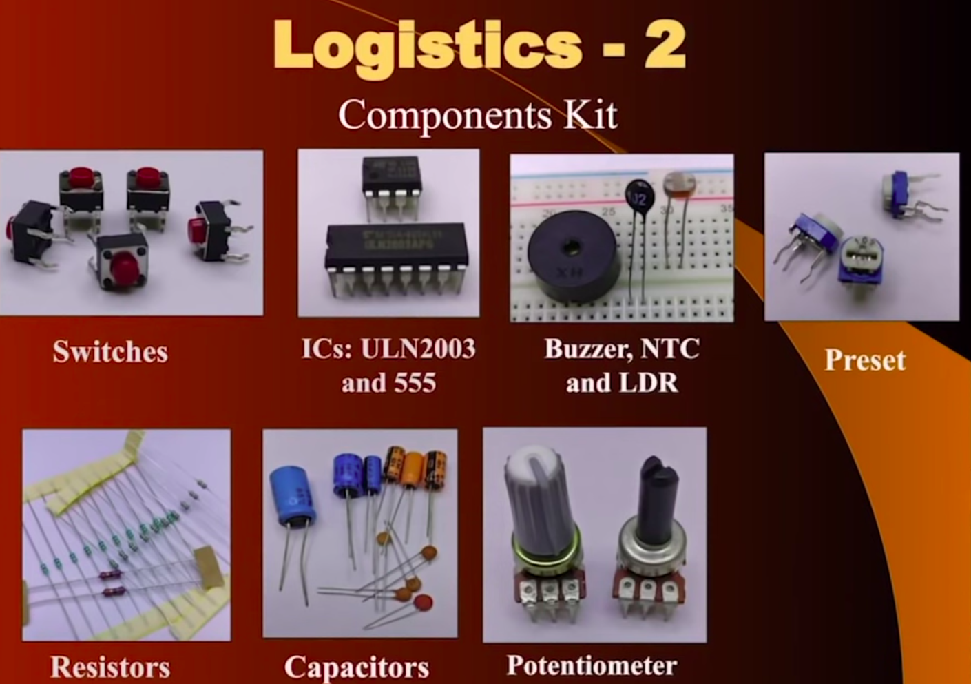
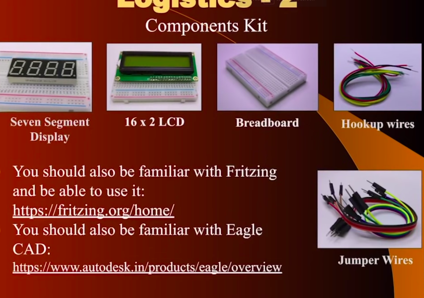
Familarity with Circuit designing softwares
Embedded System
A combination of computer hardware, software, sensors and actuators etc which is designed to perform a specific tasks.
Embedded System VS General purpose computer
| ES | GP | |—|—|project | ES are dedicated to specific tasks| Meant for general purpose | | Variety of processors can be used | Specific types of processors are used | | ES are cost sensitive | Not cost sensitive | | Operate under real time constraints | No real time, delay can be tolerated | | Also operate in extreme enviroments | Home, Office, Hospitals etc | | Usually ROM is used | RAM based | | ES are resource constrainted | Abundant resources | | ES are infrequently reprogrammed | Frequently reprogrammed | | Reliability and correctness requirements | Can be so-so |
Terms
- Computer: CPU, Memory, I/O ports.
- Microprocessor: CPU on a single chip.
- Microcomputer: Microprocessor, Memory, I/O ports on a single PCB.
- PCB: Printed Circuit Board
- Microcontroller: Microcomputer on a PCB.
- System On Chip: SOC is Microcontroller with programmable analog.
- PWM: Pulse Width Modulation
- UART: Universal Asynchonous Receiver Transmitor
- SPI: Serial Peripheral Interface
- I2C: Inter Integrated Circuit
- JTAG: Join Test Action Group
- BOD: Brown Out Detector (For reset)
- DSP: Digital Signal Processing
- BJT: Bipolar junction transistor
- LDR: Light Dependant Resistor
- ESR: Equivalent Series Resister
- TCXO: Temperature Compensated Crystal Oscillator
- IrDA: Infrared Data Association
- SBW: Spy-Bi-wire (SWD) Serial Wire Debug
First Microcontroller in 1974 TMS1000 by Texas Instruments 4 bit.
Demonstration of MSP430 Based Projects
Implementation of Embedded system
Methods using:
- General purpose processor
- Application specific processor
- Single purpose processor
Architectures:
- Von Neumann Architecture
- Harward Architecture
Instruction set architecture
- CISC: Complex Instruction Set Architecture
- RIDC: Reduced Instruction Set Architecture
Program: Sequence of Instruction Instruction: Atomic command that processor uderstands
Opcode + Operand
ADD R1, R2
Microcontrollers:
- CPU: 4/8/16/32/64 bit microprocessor (CISC, RISC, VN, HARWD)
- Memory:
- ROM/EEPROM/FLASH - Program storage
- Volatile Memory RAM/FRAM - Data storage
- Digital Input/Output pins
- Communication Interfaces
- Peripherals
- Timers, Counters, PWM generators
- Watchdog timer with indepedent oscillator
- Analog to Digital Converter (ADC)
- Digital to Analog Converter (DAC)
- 6 to 200+ pins
Features of Modern MCU
- Fully programmable pins I/O.
- Output pins with 30-40 mA Source/Sink current capacity.
- Input pins with weak and strong pull up resitors or tri state capacity.
- Each pin offers multiple functions one of which can be selected.
If no RAM is used then RISC architecture is preferred. By using hardware stack.
Semi constants: Value which is constant most of the time but changes are made once in a while. Which is stored in EEPROM.
Elements of Microcontroller Ecosystem
- Clock
- Reset
- Power supply
- Program download ability
Clock
Digital system designing:
- Synchronous
- Asynchronoous
555 timer chip is used for generating clock.
Ring Oscillator
Frequency =                     1
                _____________________________________
            2 * T(Delay peroid) * N(Number of diodes)
Crystal frequency = 32678Hz
Power supply in Embedded systems
Using Capacitive voltage divider:
Advantage:
Uses capacitors and less spacious than transformer.
Disadvantage:
Human interaction should be minimum because of shock!
Switching Mode Supply
Used in phone and laptops.
Voltage Regulator
- Linear Regulator
- Switching Regulator
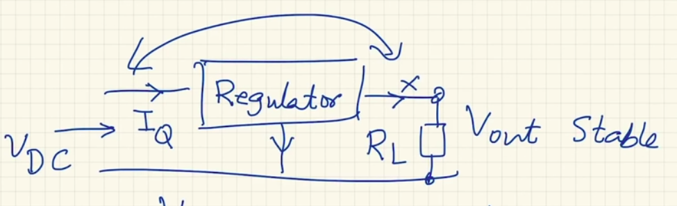
Linear regulators
BJT works in forward active region. The classic series 78xxx.
Example 7805 transitor which provides 5V output.
Issues: They require large dropout voltage and large quiescent current I(q).
Large dropout voltage V(Dropout) = V(in) - V(out) Which has to be V(D) > 3V
Large quiescent current I(q) = Even if there is no load connected to V(out) the linear regulator consumes some amount of current. That current is I(q). Which comes out of ground terminal of transistor.
V(D) = 3V I(q) ~ 10mA
Solution: Low drop out LDO linear regulators.
V(D) = 0.1V I(q) = 10-100uA
Simplest regulator uses Zener diodes.
A great playlist for Basic electronics.
Darlington pair
LM317 IC for variable Voltage.
Switching regulators are used instead of linear regulators.
Advatage:
90%+ efficiency
Types:
- Buck (Bend)
- Boost
- Buck-Boost
Switching Buck Regulator
A buck converter or step-down converter is a DC-to-DC converter which steps down voltage from its input to its output.

L is current
So, when the switch is on, across the inductor the voltage is VL = Vin - Vout
The current in the inductor rise at a rate of (Vin – Vout) / L
Introduction to MSP430
- Mixed Signal Processor
- 16 bit processor
- Address bus: 16 or 20bit. 2^16 addresable memory locations.
- Data bus: 16 bits.
- Designed for low power applications.
- RISC Architecture.
- Von neumann Memory architecure.
- Five Low Power Modes(LPM0-LPM4).
Can be used as:
- General purpose sensing and measurement.
- Capacitive touch sensing
- Ultrasonic range sensing.
More than 500 microcontrollers in this MSP430 series.
JTAG
Joint Test Action Group 4 wire serial protocol
- TMS - Test Mode Select
- TDO - Data Output
- TDI - Data Input
- TCK - Clock
- TRST - Test Reset
- TAP - Test Access Port
MSP430G2553
- Contains 28 pins
- RISC Architecture
- 27 core instructions
- 7 Addressing mode
- Register Mode
- Indexed Mode
- Symbolic Mode
- Absolute Mode
- Indirect Register Mode
- Indirect autoincrement
- Immediate Mode
- 16 bit Address bus. 2^16: 65K(65,536)
- 16 bit Data bus
- 16MHz clock speed
- Von neumann Memory Architecture
- Little endian: When LSB is stored first and MSB comes second
- 1 word = 2 bytes = 16 bits
- 16 Registers:
- 4 Special purpose:
- Program Counter
- Stack Pointer
- Status Register
- Constant Generator
- 12 general purpose
- 4 Special purpose:
Physical Interfacing:
Connecting Inputs and Outputs.
Inputs:
- Switches
- Switch matrix
Outputs:
- LED
- 7 segment display
- LCD
Terms:
- MPMT: Multiple Pool Multiple Throw
Calculation for resistor values on Pull up resistors.
How to reduce switch bounce?
Switch matrix interface?
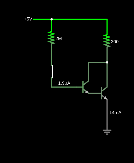
To increase the current from MCU which is 6mA NPN transistor is used.
BC 547
- Max(100mA)
- Saturation(0.1V to 0.2V)
- NPN Transistor
Forward Active region
Common collector
Beta of transistor
LED to remain constant even when system is powered via battery.
BC557
- PNP Transitor
- Max(100mA)
Transistors can anplify